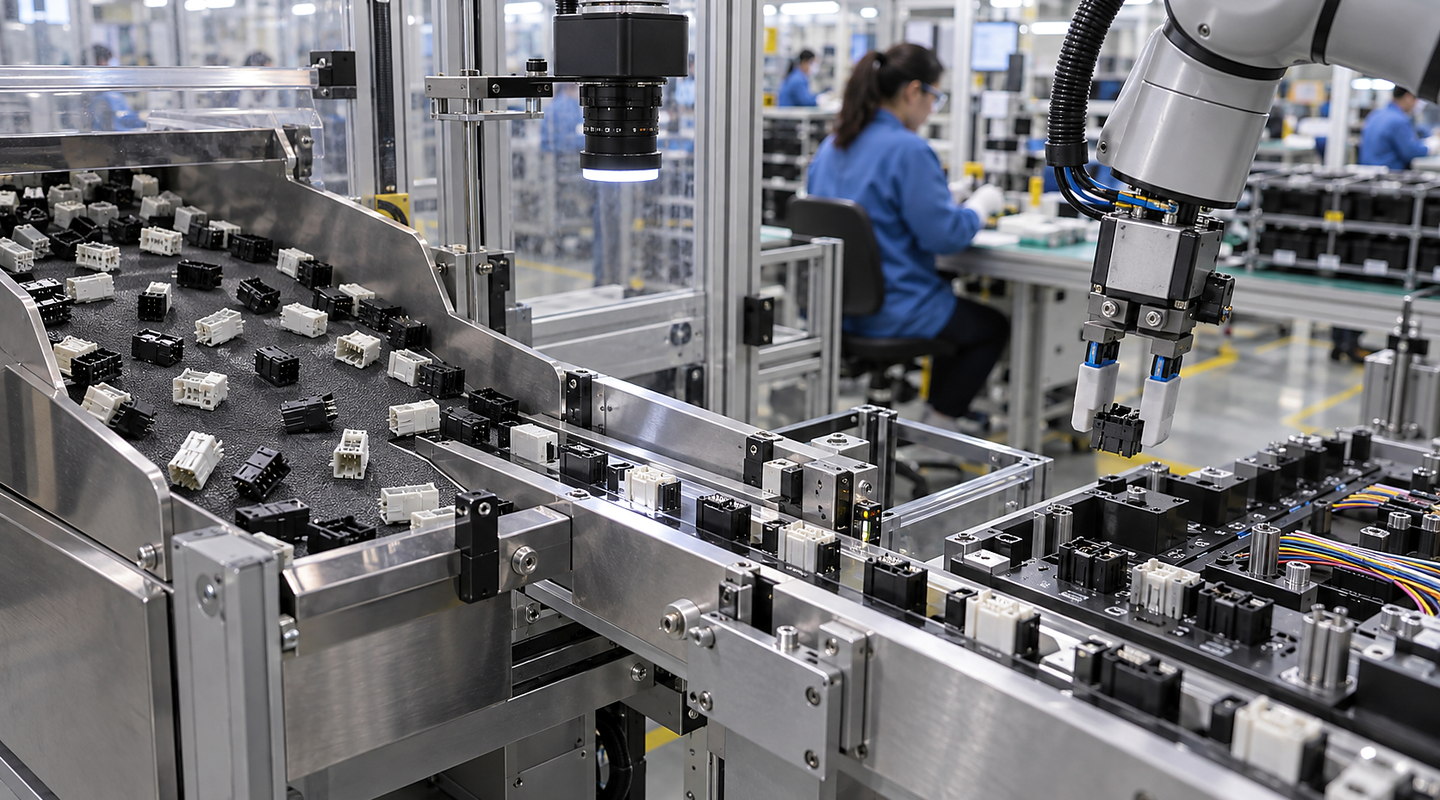
Electrical Contact Feeders: How the Process Works
Plan electrical-contact feeding trials around protected features, bulk variation, interlocked parts, insertion orientation, one-part release and damage checks.
An electrical-contact feeder should deliver one undamaged contact in the pose required for insertion or assembly. Mark protected functional and plated surfaces, provide representative delivery packaging and bulk parts, and trial separation, track travel and final release. Judge usable delivery together with deformation, mixed variants, missed or double parts and recovery.
Use the contact and downstream interface checklist and damage-aware acceptance record. Mechanical feeding and visible-condition checks do not replace any required electrical or functional testing.
Understand the complete route from input to accepted output — Electrical Contact Feeders
Plan electrical contact feeders around real component variation, bulk condition, orientation, usable delivery rate and the downstream interface. Discuss representative part trials with Sorting Solutions. Follow the material or part through each operating step and include recovery, cleaning and change in the real cycle.
Discuss your application

Four clear stages for electrical contact feeders
At each stage, you can review how component geometry and variation for electrical-contact orientation & feeding and jam, damage and recovery acceptance checks affect the next commitment.
- 01
Review Representative Production Components
Provide normal, marginal and supplier-variant contacts with their sample-batch identity. Mark mating faces, spring features, locking lances and plated areas, distinguishing permitted support surfaces from areas that must not be rubbed or loaded. Confirm loose, tray or carrier-strip delivery and normal bulk condition.
- 02
Trial Separation, Orientation and Presentation
Observe nesting and interlocked parts before selecting handling or tooling. Include difficult pairs in the trial and inspect contacts after separation and track travel. Record deformation, surface marks, recirculation and interventions separately from correctly oriented output.
- 03
Develop Tooling, Controls and the Downstream Interface
Define leading end, upper face and rotation using the receiving assembly-tool datum. Agree release position, permitted movement, delicate-part support and part-present confirmation with the assembly integrator. Review how an inverted contact or similar wrong variant is distinguished without assuming an unproven detection method.
- 04
Challenge Delivery, Replenishment, Jams and Recovery
Challenge absent and double parts, normal replenishment, the smallest intended batch and a downstream station that pauses unexpectedly. Compare incoming and fed samples, recording correct orientation, damaged features, mixed variants, missed deliveries and recovery. Measure usable delivery at the insertion point.
Decisions and results stay connected
| Stage | What happens | What you can review |
|---|---|---|
| Review Representative Production Components | Provide normal, marginal and supplier-variant contacts with their sample-batch identity. Mark mating faces, spring features, locking lances and plated areas, distinguishing permitted support surfaces from areas that must not be rubbed or loaded. Confirm loose, tray or carrier-strip delivery and normal bulk condition. | Identified contact batches, delivery form and protected/permitted handling surfaces. |
| Trial Separation, Orientation and Presentation | Observe nesting and interlocked parts before selecting handling or tooling. Include difficult pairs in the trial and inspect contacts after separation and track travel. Record deformation, surface marks, recirculation and interventions separately from correctly oriented output. | Separation, entanglement, surface-condition and deformation observations with intervention records. |
| Develop Tooling, Controls and the Downstream Interface | Define leading end, upper face and rotation using the receiving assembly-tool datum. Agree release position, permitted movement, delicate-part support and part-present confirmation with the assembly integrator. Review how an inverted contact or similar wrong variant is distinguished without assuming an unproven detection method. | Receiving datum and pose, release/support interface, part-present requirement and unresolved variant checks. |
| Challenge Delivery, Replenishment, Jams and Recovery | Challenge absent and double parts, normal replenishment, the smallest intended batch and a downstream station that pauses unexpectedly. Compare incoming and fed samples, recording correct orientation, damaged features, mixed variants, missed deliveries and recovery. Measure usable delivery at the insertion point. | Damage-aware results, downstream availability, replenishment and exception/recovery observations. |
Keep connected responsibilities clear
Your final electrical contact feeders scope must also account for escapement and downstream pick interface, jam, damage and recovery acceptance checks, current regulations and the conditions at your site.
- Sample trials must include normal, marginal and supplier-variant components.
- Quoted feeder output is not the same as usable delivery at the downstream process.
- Fragile, flexible, magnetic or entangling parts may need a different presentation method.